
Finite Element Method Analysis Of A Jaw Structure Upon Surgically Assisted Rapid Maxillary Expansion With Various Surgical Procedures
INTRODUCTION
Recently number of patients who have been suffering from dentofacial disharmony is increasing1. Among these patients quite a few of them suffer from maxillary transverse deficiency needing correctional treatment for transverse disharmony between upper and lower jaw bones and malocclusions2. Among correctional treatments, surgically assisted rapid maxillary expansion is a treatment of choice3-6.
To help transverse expansion of palatine bones various methods of osteotomy for upper jaw bone has been suggested. Hyrax (Hyrax Orthodontic Expander, ExpoOrtho) device is used to expand the maxilla and the stresses are generated in the maxilla due to the applied force7. For stress and displacement analysis of maxillary expansion, different material properties can be incorporated in Finite Element Method (FEM) analysis according to patient’s sex and age. With the conditions using FEM, distributions of stress and displacements developed on maxilla have been analyzed for osteotomy and without clinical procedure the locations can be determined where patient can feels pain8-9. In this paper, FEM was used to predict and analyze the developed stresses by maxillary expansion which can help to improve the surgical methods. To develop simulated conditions the same force was exerted on maxilla through Hyrax and same conditions for different methods of osteotomy were employed in commercially available FEM software ANSYS V14.0.
Method
2.1- Development of FEM model
A Three-Dimensional (3-D) prototype of maxillary model was produced by taking the impression on a plaster of a volunteer patient. The model was also scanned with a KCI 3D scanner (Korea Computer Information Co., Ltd, South Korea). The data generated of 353,230 nodes by the scanning was incorporated in commercial software for 3-D reverse engineering called RAPIDFORM V6000 (Rapidform, Inc. Sunnyvale, CA). RAPIDFORM converted the 353,230 nodes into 3-D volume of 117703 elements for FEM analysis. The model generated by RAPIDFORM was used to create a virtual 3-D structure as shown on Figure 1.
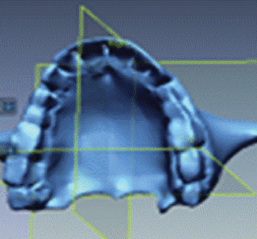 Figure 1: 3D volume element generated using RAPIDFORM
A device Hyrax (Hyrax Orthodontic Expander Stainless Steel made) was fabricated for the application of rapid maxillary expansion as shown in Figure 2. The device was activated with central
 Figure 2: Shape of Hyrax
expansion screw. Each 1/4 turns of screw caused transverse expansion of 0.25mm. With intermittent turning of the screw in a time sequence an expansion was made to left and right in due turns. Actual operation of Hyrax was applied by assuming one full turn (4 of 1/4 turn) corresponding to 1mm expansion. Reaction forces were computed with these conditions using commercially available finite element software ANSYS V14.0.
The hyrax is generally made of stainless steel. The material properties of tooth, bones and AISI Type 403 stainless steel Hyrax were used in 3-D finite element model as listed in Table 1-2. Based on the analysis of stress distribution and displacement using FEM, the optimum surgical methods were determined. One control
 Table 1: Properties of AISI Type 403 Stainless Steel Hyrax 10-11
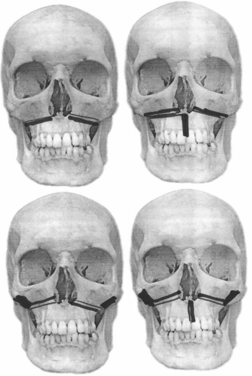 Figure 3: (1) Le-fort I Osteotomy (2) Para-median Osteotomy (3) Pterygomaxillary separation and (4) para-median Osteotomy and Pterygomaxillary separation.
group and four test groups (as shown in Figure 3) were formed and the experimental material properties provided to software as tabulated in Table 2.
 Table 2: Experimental Conditions of test groups and control group
Control group: No surgery
Test group: With surgery
- Test 1: Le-fort I Osteotomy
- Test 2: Le-fort I Osteotomy + Para-median Osteotomy
- Test 3: Le-fort I Osteotomy + Pterygomaxillary separation
- Test 4: Le-fort I Osteotomy + Para-median Osteotomy + Pterygomaxillary separation
Stresses and strains induced at the maxilla under each condition listed above were evaluated for the comparative analysis. Also the stresses generated in the Hyrax are shown in Figure 4. In the control group no
 Figure 4: Stress distribution & reaction forces using ANSYS on Hyrax
surgical operation was applied, simple induced stress and strain distributions by Hyrax were analyzed with FEM. Appropriate boundary conditions were applied in FEM analysis to properly represent the three surgical methods. Von-Mises theory was adopted to analyze the stress distribution 7. In addition to analysis of maxilla model the displacements of the first molar and premolar were also considered along y and z-axis.
Results
The average displacement value (both left and right sides) at first molar and premolar was 0.326×10⁻²mm.
In Figure 5, results of induced stress were shown. The
 Figure 5: a) Displacement of Control group
           b) Stress distribution of Control group
largest stress around this area was 268.66×10⁻³kgf /mm2. For Test 1, upon the applications of Le-fort I osteotomy the displacements at first molar and premolar on right and left sides were similar which were 0.723×10⁻² mm for each as shown in Figure 6(a). Stresses developed on the right and left sides at first molar and premolar were 233.38×10⁻³kgf/mm2 which was lower compared to the values for control group as shown in Figure 6(b).
However, a stress concentration of 700×10-2kgf/mm2
 Figure 6: a) Displacement for Test 1
            b) Stress distributions of Test 1
was found at the area where pterygomaxillary separation was not applied. Similar analysis was performed for all the other three cases, the displacement and stress values are shown in Table 3 and Table 4 respectively. It was observed from the results mentioned in Table 3,
4 and Figure 7 that the maximum strain was substantially
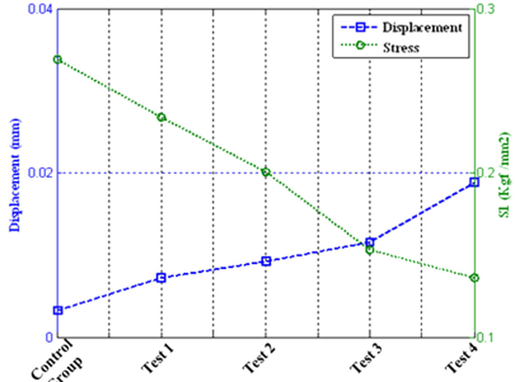 Figure 7: Displacement and stress for first molar and premolar
increased from Test 1 to Test 4 which was due to the application of pterygomaxillary separation. The maximum strain or displacement at first molar and premolar was observed for Test 4 which was 1.88x102mm on average. A stress level of 200.11×10⁻³kgf/mm2 was developed at first molar and premolar on right and left sides. Whereas, in Test 1 where pterygomaxillary
 Table 3: Displacement values at first molar and premolar
 Table 4: Stress values at first molar and premolar (S1 ), Stress values while Pterygomaxillary separations was not performed (S2 )
separation was not performed a stress concentration of 900×10-3 kgf/mm2 was observed. Le-fort I osteotomy and pterygomaxillary separation greatly relieved the level of stress to 153.03×10⁻³ kgf/mm2 at first molar, premolar and hard palate. The observed stress concentration was reduced to the level of 0.0014×10⁻³kgf/mm2 at the area where pterygomaxillary separation was applied.
DISCUSSION
In control group, without an application of the surgery simply the stresses and strains developed by the Hyrax were evaluated. The study model’s left and right maxillaries were not symmetric leading to development of asymmetrical displacements. However, considering the left and right side of maxilla from control y-axis the general trend was that largest displacement was developed at premolar and first molar on both left and right sides, at which Hyrax exerted forces. It was observed that the distributions of largest values were at hard palate area, first molar and premolar where the Hyrax was attached. The results already indicated that pterygomaxillary separation was the most effective surgical method for rapid maxillary expansion. Since all the surgical methods including Le-fort I osteotomy, pterygomaxillary separation and para-median osteotomy were applied, larger displacement was achieved compared to control and other test groups. Moreover the stress level was continuously decreased because of simultaneous surgical operation of Le-fort I osteotomy, pterygomaxillary separation and para-median osteotomy a stress level of 136.08×10⁻³ kgf/mm2 was developed at first molar and premolar, also reduced stress concentration of 0.0012×10⁻³ kgf/mm2 was observed. It is suggested that 3-D FEM analysis technique along with Hyrax can be used to determine the stresses and displacement developed on the maxilla without actually performing surgical operations. Using 3-D FEM analysis, stresses and strains can be theoretically evaluated. Moreover, by supplying different bone properties for different patients, various analyses can be customized for a specific patient revealing all the characteristic nature of the problems. The results of the analysis can be visually confirmed in detail.
CONCLUSION
This study analyzed the strains developed at the maxilla, the stresses and the reactions which were generated during rapid maxillary expansion, for which a small stress applying device, Hyrax, was used and also the four different surgical methods were employed. When all the results were combined and analyzed the Test 4, where the three surgical methods were jointly applied showed the largest strains and the smallest stress compared with the control and other test group. The combined surgical method (Test 4) was the most desirable method which can minimize patient’s pains and maximize the expansion during rapid maxillary expansion. The application of pterygomaxillary separation had great effect on strains and stress.
ACKNOWLEDGMENTS
The authors would like to acknowledge Higher Education Commission of Pakistan to provide scholarship for higher studies.
REFERENCES
- Parrello D, Bolamperti L, Caprioglio A. Interdisciplinary treatment of Class III malocclusion: a case report. Prog Orthodont, 2011; 12: 169-179.
- Yang CY, Min SK, Oh SH, Kwon KH, Lee J, Cha JW. Clinical study of surgically assisted rapid maxillary expansion. J Kor Assoc Oral Maxillofac Surg, 2005; 31: 60-69.
- Stromberg C, Holm J. Surgically assisted rapid maxillary expansion in adults. A retrospective longterm follow-up study. J Craniomaxillofac Surg, 1995; 23: 222-227.
- Lines PA. Adult rapid maxillary expansion with corticotomy. Am J Orthodont, 1975; 67: 44-56.
- Moss JP. Rapid expansion of the maxillary arch I. J Pract Orthodont, 1986; 2: 165-171.
- Progrel MA, Kaban LB, Vargervik K, Baumrind Surgically assisted rapid maxillary expansion in adults. Int J Adult Orthodont Orthodont Surg, 1992; 7: 37-41.
- Jafari A, Shetty KS, Kumar M. Study of stress distribution and displacement of various craniofacial structures following application of transverse orthopedic forces–a three-dimensional FEM study. Angle Orthodont, 2003; 3: 12-20.
- Holberg C. Effects of rapid maxillary expansion on the cranial base an FEM analysis. J Orofac Orthoped, 2005; 66: 54-66.
- Kennedy JW, Bell WH, Kimbrough OL, James WB. Osteotomy as an adjunct to rapid maxillary expansion. Am J Orthodont, 1976; 70: 123-137.
- Harvey PD (ed). Engineering Properties of Steels, American Society for Metals, Metals Park, OH, USA, 1982.
- Peckner D, Bernstein IM (eds). Handbook of Stainless Steels, McGraw-Hill Book Company, New York, USA, 1977.